Home / Electronics / K70 Encoder Swap
K70 RGB Pro volume wheel encoder swap
The keyboard I use is a Corsair K70 RGB Pro (with MX blues if you're curious), and overall I love it, but there's one thing that really bothered me: the volume encoder wheel has no detents.
In my quest to correct this terrible injustice, I opened up the keyboard and discovered that the encoder is a Kailh EN65xx series, basically the same kind of encoder used for scroll wheels in mice. I looked on their website, and sure enough, a variant with detents was available: CEN652812R01.
I could only find them on Aliexpress, so I ordered a pack of 5 for about $8. When they finally showed up, I desoldered the wires from the old encoder, noting which ones went where, and soldered them to the new one. It worked almost perfectly, with one glaring issue: each detent registered as two increments in Windows. With the old encoder, the volume wheel changed the volume in increments of two, but the keyboard was designed to be able to handle single steps, i.e. 00 → 01 is one increment. The new one undergoes a full cycle per detent: 00 → 01 → 11 → 10 → 00. The result is that a single detent changes the volume by two steps of two, i.e. 0/100 to 4/100.
This does work perfectly fine, but I'm one of those people who likes their volume set to multiples of 10. With increments of 4, I can only set it to even multiples of 10: 20, 40, 60, 80, and 100. If I wanted to go from 60 to 70, the closest I could get is 68 or 72.
Of course, I immediately got to work in KiCAD designing a little "translator" board that would read the input encoder's position and sort of cut the steps in half, registering one full cycle as a single state change. I originally intended to use a PIC10/12 so I could get some more practice in PIC assembly, but I ultimately went with an Attinyx5 programmed with the Arduino IDE.
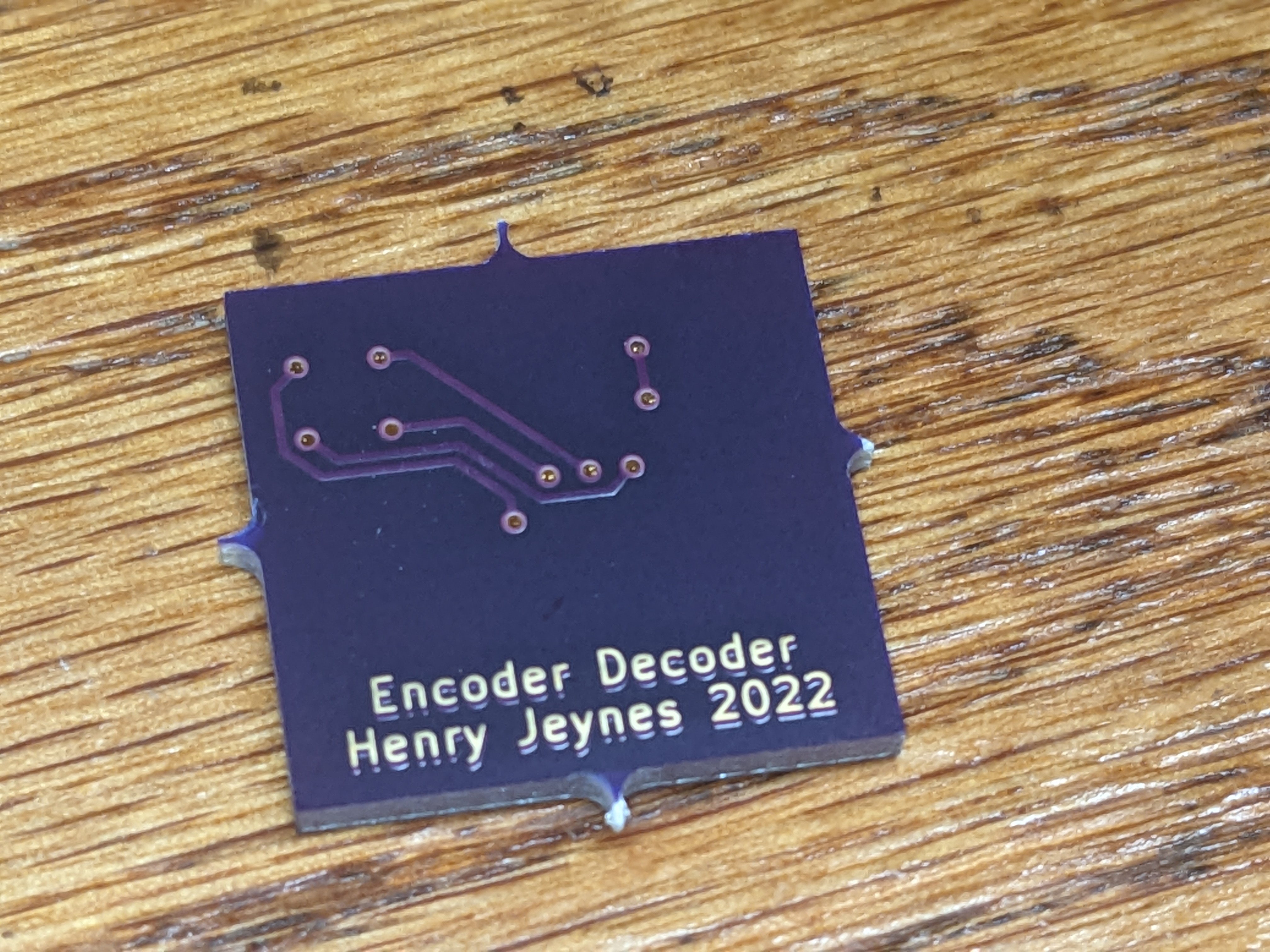
You can see that I tried a funky 3D-ish text design on the back. I did this using two copies of the text on the copper layer, one offset down slightly, and one copy of the text on the solder mask. The gold-plated copper shows through the mask.
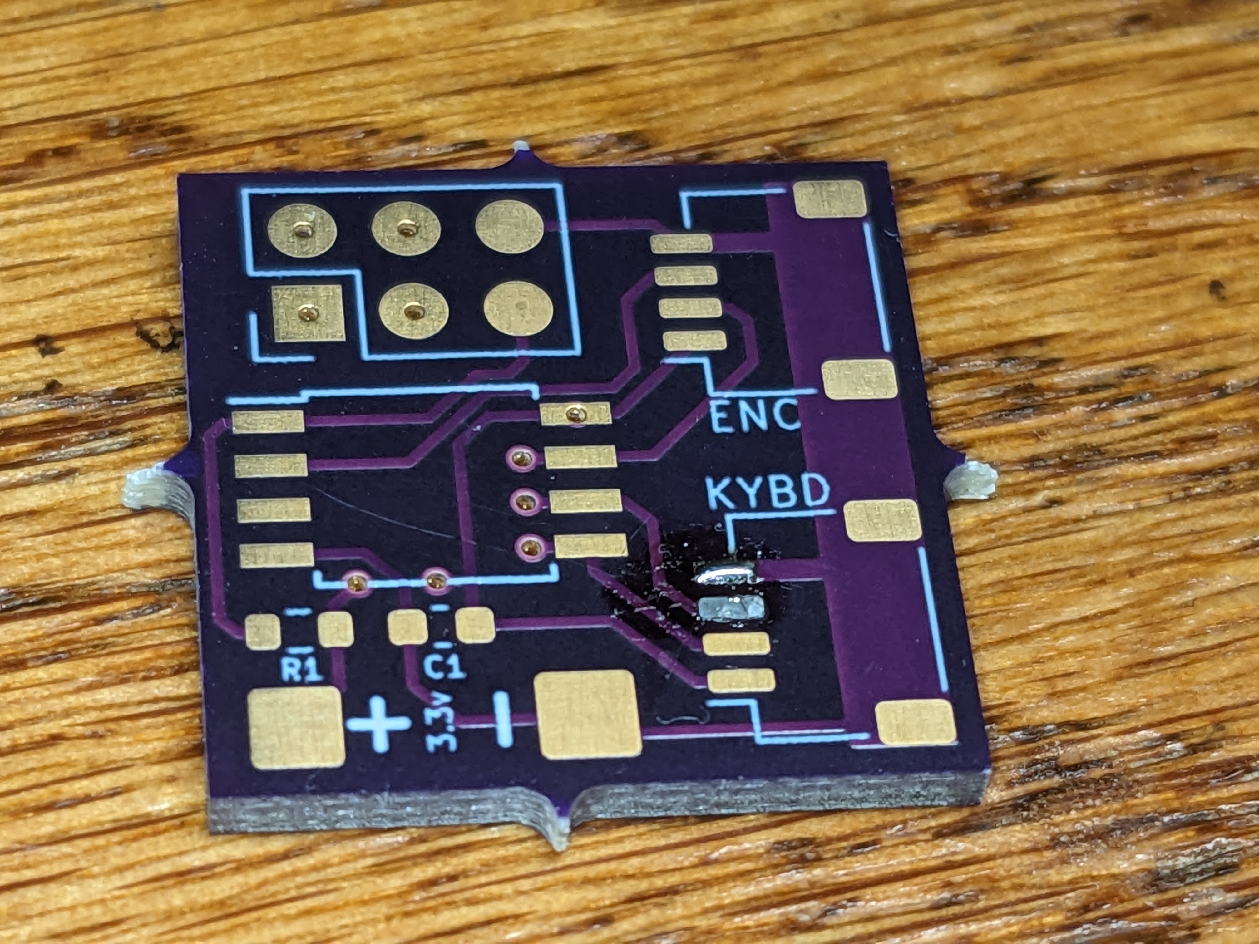
The board takes 3.3V from a couple of test points on the keyboard's PCB. Power draw is negligible, especially because that voltage limits the clock speed to 8MHz.
The ENC and KYBD connectors are both 4-pin JST-PH 2.0. This same connector is used in SparkFun's Qwiic system, which makes for a very convenient source of both the SMD connectors and the female-female cable needed to connect the PCB to the keyboard.
There are a couple of design errors. The biggest one is that the 3.3V input is shorted out by the encoder connections somewhere along the line. This can be worked around, but ultimately I need to fix that in the next revision (if there is one).
July 2023: I finally finished up this project! The last big hurdle was the code, because for some reason it just broke my brain. I'm still not 100% sure why it works, but my volume now changes by 2 steps per detent, as God intended.
I never did make a second revision of the board. The issue turned out to be that the encoder connector had connections to GND on both of the outer pins, not +3.3V and GND like I thought when I designed it. I simply cut the offending wire out of the cable.